Robert F. Bourque, Ph. D., P.E.
Bourque Engineering LLC
Los Alamos, New Mexico USA
bob@rfbourque.net
505-412-0194
Chapter |
Title |
1 |
|
2 |
|
3 |
|
4 |
|
5 |
|
6 |
|
7 |
|
8 |
|
9 |
|
10 |
|
11 |
|
12 |
|
13 |
|
14 |
|
15 |
|
16 |
|
17 |
|
18 |
|
19 |
|
20 |
|
21 |
|
|
|
|
|
|
A Compact Pollution-Free
External Combustion Engine
with High Part-Load Efficiency
Previous Chapter | Next Chapter
13. Expander Piston Structural Analysis
The ASME Boiler and Pressure Vessel Code Section VIII was used to evaluate stresses at operating temperature for the Expander pistons, cylinders, and cylinder head bolts [25]. Bearing sizes were established using applicable vendor load ratings.
|
|
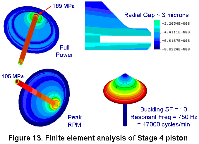
An unusual aspect of the Expander is the “loudspeaker” piston shape in the two low-pressure stages, chosen because of their high stiffness despite thin walls. These required finite element analysis to determine stresses, deflection, buckling, and resonant frequency. Figure 13 shows results for Stage 4. This is the most problematic stage because this piston must be as thin as possible for minimum mass. In fact, to match it for balance, the other stages require ballasting.
The Expander speed is set so that peak acceleration loads roughly match steam pressure loads at full throttle. Fortunately, these loads never occur at the same time and therefore can be evaluated separately.
At the top left of Figure 13 is stress from the full power load. The maximum is 189 MPa (27 ksi) appearing at the rod/piston junction. This is acceptable even at high temperature because it is very localized bending (and it could be designed away). Below that image shows stress from peak acceleration, which occurs at the bottom of the piston rod. The 105 MPa (15 ksi) peak is acceptable, and is in the low temperature region.
Another issue is the possibility of the piston to deflect away from the cylinder wall due to pressure, causing blowby. As seen at top right in a magnified cross section of the seal slot, the gap from inward deflection is only about three microns.
Lastly, problems would occur if the piston resonant frequency were near any operating frequency, or if the cone buckled under full-pressure load. As seen in the bottom right, the resonant frequency is much higher than peak rpm, and there is ample buckling safety factor (SF).