Robert F. Bourque, Ph. D., P.E.
Bourque Engineering LLC
Los Alamos, New Mexico USA
bob@rfbourque.net
505-412-0194
Chapter |
Title |
1 |
|
2 |
|
3 |
|
4 |
|
5 |
|
6 |
|
7 |
|
8 |
|
9 |
|
10 |
|
11 |
|
12 |
|
13 |
|
14 |
|
15 |
|
16 |
|
17 |
|
18 |
|
19 |
|
20 |
|
21 |
|
|
|
|
|
|
A Compact Pollution-Free
External Combustion Engine
with High Part-Load Efficiency
Previous Chapter | Next Chapter
11. Description of the Expander
Many types of expanders were examined for this engine: turbines, rotaries, and several types of reciprocating. In the end the last was chosen using the standard connecting rod/crank configuration and flathead valves. The others seemed appealing at first. But all had flaws when examined in detail. For example, steam turbines are too small at vehicle power levels. Rotaries, and sliding valves, have difficulty dealing with very high steam pressure.
|
|

Figure 8 shows a longitudinal cut through the expander. An inline version is shown for convenience, although V and horizontally-opposed options are certainly possible.
At the bottom is an oil-filled crankcase at near room temperature. The connecting rod and crank bearings are journal, while the main bearings are roller. (Roller bearings are usable here because the oil should remain contamination-free for a very long time. In IC engines, stress risers for combustion particulates can shorten roller bearing life.) Long pushrods are shown. These provide thermal isolation and space for several seals. As shown later, each seal has its own purpose.
The two high-pressure pistons are solid while the other two are conical, a stiff geometry suitable for thin walls. Each cylinder head is independent to avoid stresses due to thermal expansion. The back side of each piston is at its exhaust pressure. Because of the low expansion ratios, this noticeably reduces the load on the pushrods and crank.
|
|
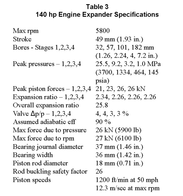
Specifications, reformatted from the code output, are given in Table 3 for the 140 hp Expander. The Expander is discussed in more detail in the following paragraphs.
Some comments on Table 3:
- The peak rpm is chosen so that the full power piston force on the crank is about the same as the rotary force at peak rpm. These forces never act at the same time.
- The valve losses of 3-4% are less than the assumed adiabatic losses of 10%, allowing room for other losses.
The total force on each piston is about the same, which should enhance smooth operation.
|
|
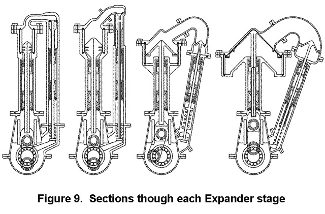
Figure 9 shows transverse cuts through each Expander stage with one of the two valves shown. The sliding crossheads, visible near the bottom, eliminate any side thrust on the piston and piston rods.
The camshaft runs at crank speed. Actually only two cams, intake and exhaust, are needed. They can be placed on the crank. Pushrod (and pullrod) mechanisms deliver the motion to the valves. The intake valves open outward, allowing steam pressure to enhance their seal during expansion. However, as is shown below, there is no pressure differential across them when they open.
|
|
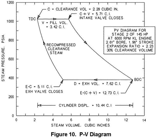
Shown in Figure 9 are the flathead valves and high clearance volumes. The latter would be difficult with high expansion ratios; but pose a minor inconvenience with low ratios. Figure 10 shows, in a P-V diagram, why this is so. Flathead valves eliminate mechanisms and bearings in the hot steam region, which would be difficult to lubricate.
The engine shown in Figure 10 is slightly different, but the features are the same. Because of the 30% clearance volume, with an expansion ratio of 2.23 the cylinder displacement must be increased from 7.62 cubic inches, as would be needed with zero clearance volume, to 10.44 cubic inches, a 37% increase. This requires an 11% increase in bore and stroke, not a serious issue. With higher expansion ratios, the required increase in displacement would be much greater.
The resulting recompression at the end of the exhaust stroke places the steam at the fill pressure, equalizing it across the intake valve when the valve opens. This eliminates turbulent losses across the valve.
|
|
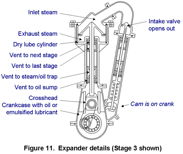
More Expander details are shown in Figure 11. Four seals are shown, which are intended to keep steam and oil separated.
In fact, some mixing is inevitable over time, and this is directed to a trap that is periodically emptied. This is as close as it comes to changing oil. Very high quality oil can be used because there is no source of contamination other than water, which should be minor because of the seals, and will likely evaporate. Oil change intervals can therefore be very long.