Robert F. Bourque, Ph. D., P.E.
Bourque Engineering LLC
Los Alamos, New Mexico USA
bob@rfbourque.net
505-412-0194
Chapter |
Title |
1 |
|
2 |
|
3 |
|
4 |
|
5 |
|
6 |
|
7 |
|
8 |
|
9 |
|
10 |
|
11 |
|
12 |
|
13 |
|
14 |
|
15 |
|
16 |
|
17 |
|
18 |
|
19 |
|
20 |
|
21 |
|
|
|
|
|
|
A Compact Pollution-Free
External Combustion Engine
with High Part-Load Efficiency
Previous Chapter | Next Chapter
15. Other Engine Components
The other primary engine components are the Burner, Steam Generator, Regenerator, Condenser, and Feedpump. These are discussed below.
|
|
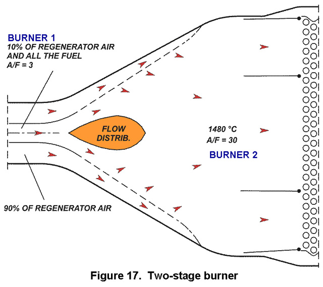
Burner. The two-stage Burner is shown in Figure 17. Fuel is injected into Burner 1 with some of the hot air from the Regenerator. There it partially vaporizes and a small amount ignites. This results in a mix of liquid and vaporized fuel, hydrogen and CO, all quite hot. When it enters Burner 2, where it mixes with plenty of also hot air, it ignites quite readily. The air/fuel ratio in Burner 2 is about twice stoichiometric, providing enough air to completely burn the fuel. A combustion temperature sensor keeps the temperature just below that where nitrous oxides form, irrespective of the type of fuel being used. Two-stage burners have already been tested by NASA and DOE and do show very clean burning of the fuel [26].
|
|
Steam Generator. All of the heat exchangers are of conventional design and based on well-established experimental heat transfer and flow friction data [27]. These data were imported into the engine software described above.
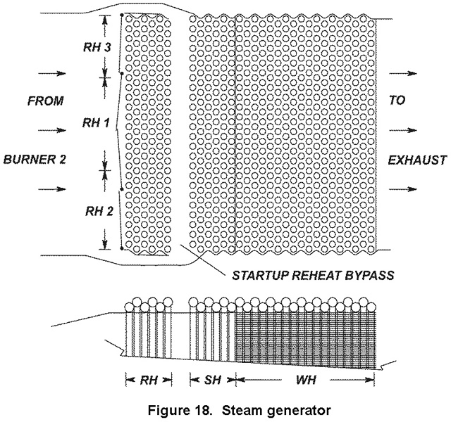
The Steam Generator is shown in Figure 18. It is made up of five sets of tubes, which are discussed below.
The tubes are connected by manifolds at each end. The manifold arrangement is established by the software to provide enough flow pressure drop though the tubes for reasonably high heat transfer coefficients, but not so much as to adversely affect thermodynamic efficiency.
The Boiler, or Water Heater (WH in the figure) raises the feedwater to saturated vapor if subcritical or about 427ºC (800ºF) if supercritical. It has staggered tubes with sheet fins.
The Superheater (SH) raises the steam to its controlled throttle inlet temperature. It has bare staggered tubes
The three Reheats (RH), placed in parallel, reheat the steam between each Expander stage. They also have bare staggered tubes. The Reheats are bypassed during startup to avoid burnout. Closure plates for this are shown in the figure as well as the bypass channels.
|
|
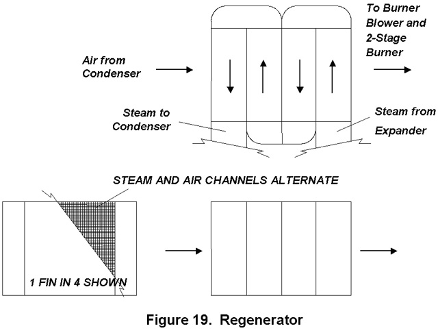
Regenerator. The Regenerator, shown in Figure 19, is a plate-fin heat exchanger that is identical on the steam and air sides except that the steam side has four passes while the air side has one. It is a major feature of the thermodynamic cycle and accounts for much of the high net efficiency. In this heat exchanger hot Expander exhaust steam is cooled to the condensing temperature by the incoming burner air.
|
|
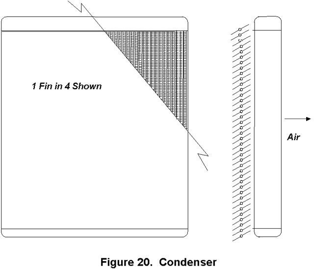
Condenser. The Condenser is shown in Figure 20. It looks like a conventional automobile radiator with vertical steam channels and horizontal fins.
It differs in that it has a set of control blinds, or a movable shade, to control air flow through it so that the condensate is subcooled to about 5ºF. Less subcooling and there could be cavitation at the Feedpump inlet. More and efficiency suffers. There may also be a separate condensate channel to separate any air that may have leaked into the system. A small auxiliary vacuum pump would remove the air.
|
|
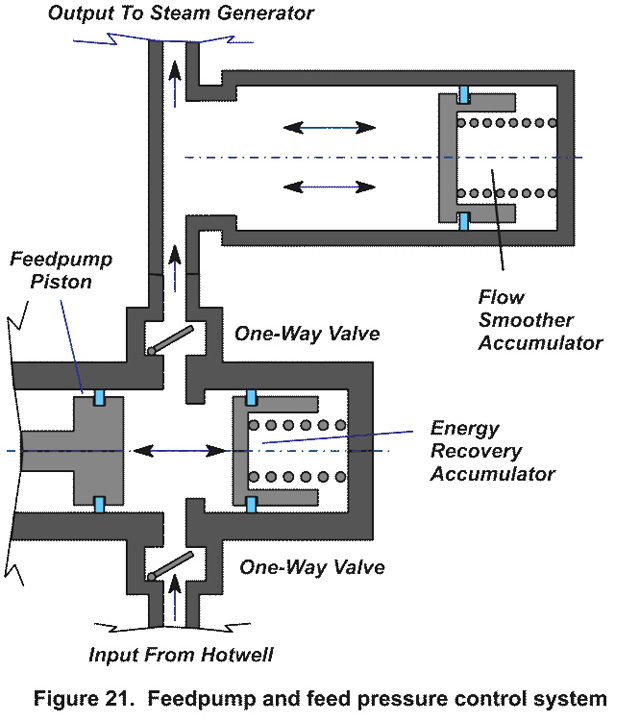
Feedpump and Feed Pressure Control. The Feedpump draws only a few hp but could be a substantial loss at part load if not controlled.
Figure 21 shows the steps taken to ensure this does not occur.
As seen, there are two spring-loaded accumulators. These are pistons held in place by long springs nearly fully compressed. Their spring constants are low enough so that the change in force over their piston strokes are small, perhaps 10%.
The Flow Smoother Accumulator serves to smooth out the flow into the Steam Generator. The Energy Recovery Accumulator comes into play at part load. When the upstream pressure is at or just above the desired value, the force on its piston becomes higher than its spring load and it is pushed back. On the return stroke, some of the stored energy is returned to the Feedpump drive and back to the Expander. Its stroke at least equals to that of the Feedpump piston. Therefore, even if the throttle were fully closed, the stored energy would simply cycle back and forth between the Feedpump drive system and the Energy Recovery Accumulator with little loss.
The Feedpump is also lubricated by the dry lubricant circulating in the system. There will be treated/coated wear surfaces here as well as in the Expander. It is known that tungsten disulfide tends to remain dispersed and does not clump. Tests are needed to determine if other lubricants, for example, graphite, do the same.