Robert F. Bourque, Ph. D., P.E.
Bourque Engineering LLC
Los Alamos, New Mexico USA
bob@rfbourque.net
505-412-0194
Chapter |
Title |
1 |
|
2 |
|
3 |
|
4 |
|
5 |
|
6 |
|
7 |
|
8 |
|
9 |
|
10 |
|
11 |
|
12 |
|
13 |
|
14 |
|
15 |
|
16 |
|
17 |
|
18 |
|
19 |
|
20 |
|
21 |
|
|
|
|
|
|
A Compact Pollution-Free
External Combustion Engine
with High Part-Load Efficiency
Previous Chapter | Next Chapter
6. Description of the Bourque Cycle
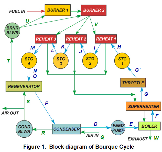
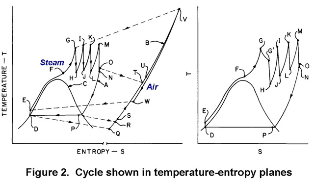
Figure 1 shows the Bourque Cycle in block diagram. The air side flow path is shown in green and the steam side in blue. Figure 2, taken from the original patent, shows the cycle in the temperature-entropy plane. The left side of Figure 2 shows the full-power steam cycle and an approximate isobar showing (not to scale) the air side. The right side of Figure 2 shows the steam cycle only with a Throttle Valve between the Steam Generator and the Expander (path G-G').
|
|
|
|
On the steam side in Figures 1 and 2, starting with the Feedpump, water enters at D from the Condenser and is pressurized to the range of 19-26 MPa (2800-3700 psia) depending on application; but is not preheated. The feedwater then enters the first stage of the Steam Generator - the Boiler (also called the Water Heater) - that has finned tubes, at E. Here the water is brought to vapor and in this case is raised to about 427°C (800°F) at F. Limiting this temperature at this point allows use of lower-cost chrome-moly steels in this section.
The steam then enters the bare-tubed Superheater where it is raised to about 593°C (1100°F) at G. It then passes through a Throttle Valve, shown on right side of Figure 2 (more on this later) and then to the Expander at G'. The Expander has four stages with Reheats between each. The multiple Reheats help to maximize average heat addition temperature.
When the steam leaves the last Expander stage at N it is still highly superheated. This energy is exploited in the Regenerator by passing it to the incoming air to the Burner. (The figure shows a state O, which is hotter than N. This was an earlier attempt to pick up friction heat, but has since been abandoned. States N and O now coincide.)
In the Regenerator the steam is cooled to saturation and even slightly condensed at P. Eliminating dry steam, which has poor heat transfer, in the Condenser makes it much easier to design that heat exchanger to fit in a vehicle. The steam is then condensed, and slightly subcooled at D.
The condensing pressure at full power is quite high, typically 0.34 MPa (50 psia), giving a full-power condensing temperature of around 138ºC (280ºF). This provides enough temperature difference with the incoming air to condense all the steam with a rather compact heat exchanger. The high Expander exhaust pressure also reduces the size of the last expansion stage; and reduces the pressure drops in the Regenerator and last Reheat to acceptable levels. Condensing pressure and temperature are lower at part load (discussed below).
On the air side, seen in green in Figure 1 and on the left side of Figure 2 as an isobar, outside air enters the Condenser at Q and leaves it heated to R. It is drawn through the Condenser Blower heating it slightly to S. It is then substantially heated in the Regenerator by the desuperheating steam to T and slightly more to about 316°C (600°F) by the Burner Blower to U. It then enters the Combustor where adding fuel heats it to its combustion temperature of 1482°C (2700°F) at V. It passes through the Steam Generator and out the exhaust at W.